|
Normally the first order of business would be to describe a range of symptoms and proceed with a proper diagnosis. But after all we’re not doctors so the heck with all that. If your heater fails to produce heat when you want and also produces heat only from the defroster vents, plenty at idle and little at higher RPMs you might just have Failed Monovalve Diaphragm Syndrome! If you suspect this to be the case then the easiest and most effective thing to do is examine the sucker!
|
||||||||||||
|
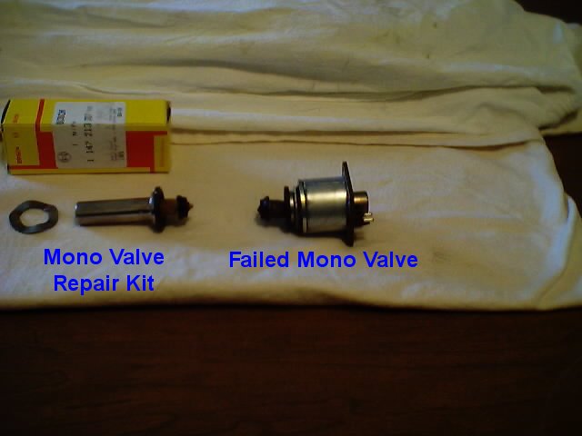
The monovalve is an electrically operated solenoid valve that is controlled by the Automatic Climate Control System. The monovalve is repeatedly opened and closed to adjust the engine coolant flow to maintain the desired heater core temperature. The monovalve consists of a body portion to which coolant hoses are connected, and a top portion that attaches with four slotted screws, a solenoid coil, and the piston valve ( the rebuild kit contains the piston valve ).
Safety
When working on any electrical component the safest bet is to “Disconnect the Negative Battery Cable before Proceeding”. If you are careful/brave or careless/wealthy then by all means disregard this caution/advice.
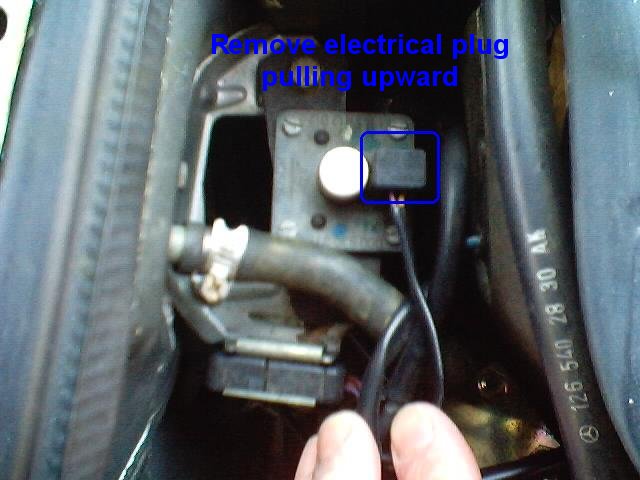
There are two wires that connect to the top of the valve body through a standard Molex two circuit connector. This connection is disengaged/separated by squeezing two sides of the connector and pulling upwards at the same time. This was can be difficult in this space and an alternative is pulling the Molex connector apart by unclipping the cap portion and removing each of the two connector pins separately and later reassembling the connector prior to replacement.
The Procedure
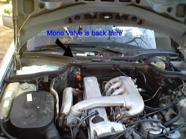
Step 1: Find your monovalve!
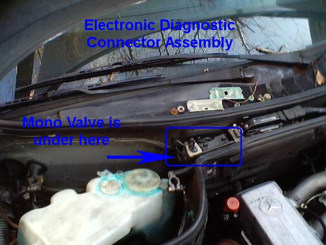
The 126 monovalve is located between the two fire walls on the passenger side. When you are facing rearward looking at the engine compartment; it is slightly to the right of the battery, slightly to the left of the engine compartment fire wall jog, and secreted immediately below an electronic diagnostic connector. Note: Please click on photos to see an enlargement. Some photos contain cautionary information.
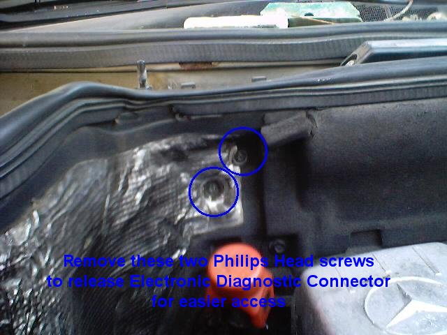
Step 2: Gain access to the monovalve!
Though not required removing two Philips head screws securing the diagnostic connector to the fire wall will allow easier access to the top of the monovalve. You can remove the monovalve electrical connection at this time by squeezing both sides of the connector and pulling up simultaneously. This can be difficult and an alternative is to proceed to the next step first.
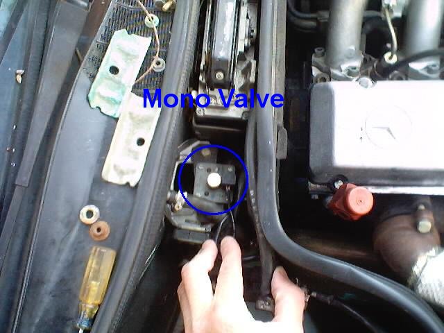
Step 3: Disassemble the monovalve!
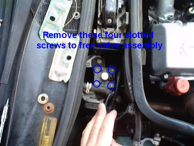
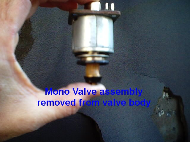
Four slotted head screws need to be removed to separate the top portion from the valve body. Care must be taken because any dropped screws will fall below and will remain essentially irretrievable without removing the battery. With the four screws removed the top portion can be removed off the valve body by grasping the cylindrical valve diaphram assembly and lifting it straight upwards. You may find it easier to remove the electrical connections at this point.
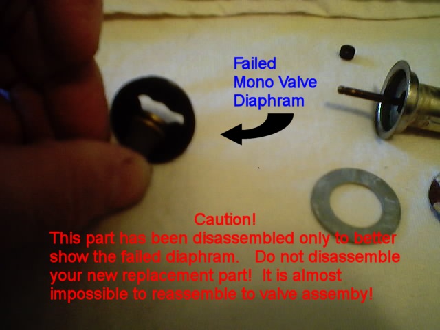
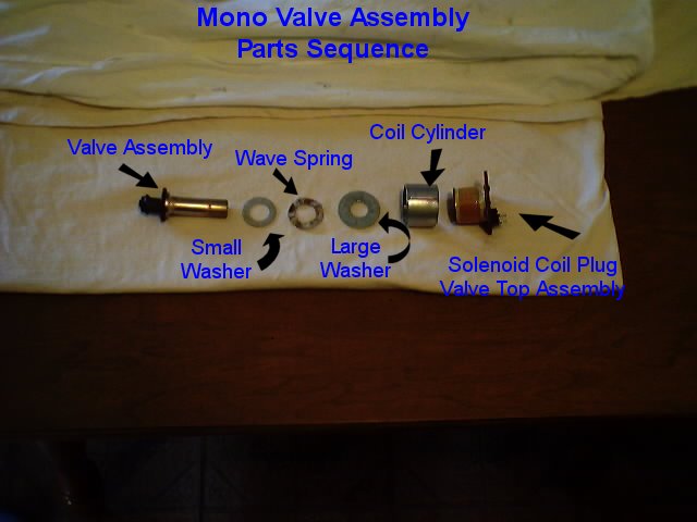
Step 4: Remove and replace the defective elements!
Surrounding the valve piston assembly will be a smaller washer, a wave spring, a larger washer, a coil cylinder and an solenoid coil/valve top/electrical plug - note the order of these parts and separate. You will most likely be able to examine the valve piston face and observe a defective rubber gasket which is the mode of failure. Take your new valve piston assembly and new wave spring and reassemble together with the washers, the coil cylinder and the solenoid coil/valve top/electrical plug in the part sequence in which you found the original.
Step 5: Reassemble the monovalve!
Place the piston valve/ spring/washer/coil group into the body of the monovalve. Reattach the electrical connectors if that is easiest. With the top portion of the valve in position and carefully insert the four slotted head screws in their respective holes and tighten gradually in a crosswise pattern until snug and secure. Reattach the electrical connector if you haven’t done so already. Reposition the electronic diagnostic connector and insert and tighten until secure the two Philips head screws.
Enjoy the climate control versatility as envisioned by your car’s Teutonic engineers! |
||||||||||||